Call us 24/7+86 17359299796
My Header Store Notice
Call us 24/7+86 17359299796
GE DS200DCFBG1BLC - Digital Control Function Board for Industrial Automation

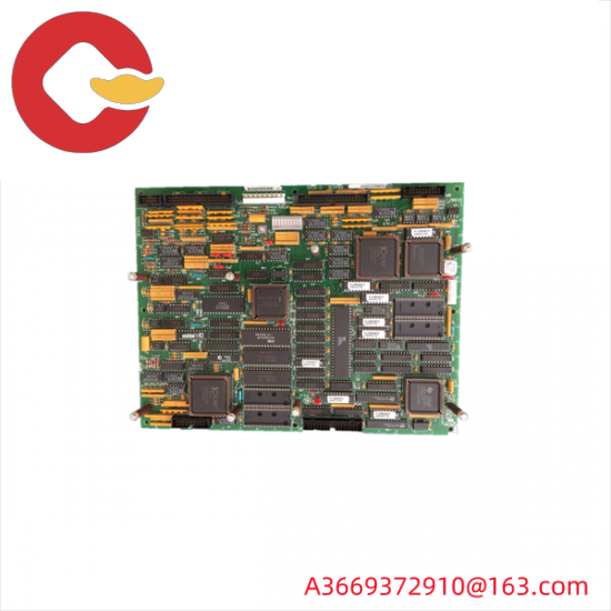
DS200DCFBG1BLC|Dc feedback power supply

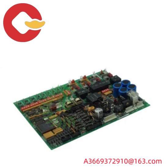
The DS200DCFBG1BLC is a power board designed by General Electric for the Mark V Series optional and replacement boards. Members of the family are cross-compatible with many GE branded shakers and drivers. The drives of DC2000, AC2000, CB2000, ME2000, and FC2000 can accept this power strip. This card provides system control level power to the driver it is mounted on and provides power to the case fan. The board’s source AC input is rated from 38 to 115 VAC. This VAC comes with a frequency range of 0 to 500 kHz, depending on the strength of the input voltage. Although the DS200DCFBG1BLC printed circuit board itself can be defined as a power board, the original power board developed in the Mark V turbine control system family was a DS200DCFBG1 power board that lacked the three important feature revisions of the DS200DCFBG1BLC product. As its extended name suggests, the DS200DCFBG1BLC Power Supply Board’s larger Mark V turbine control system family has specific applications in the management and control systems of automated drive components for wind, steam and gas turbines.
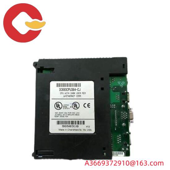
GE DS200DCFBG1BLC - Digital Control Function Board for Industrial Automation

Hardware tips and specifications

The DS200DCFBG1BLC contains a number of complex circuit systems designed to power most of the drivers. The card includes AC and DC monitoring circuit, control level power supply circuit, motor excitation power supply circuit and drive circuit. The user can configure the 12 jumpers and 7 DIP switches on the card to meet any external requirements. The Board status is communicated to the user through the onboard indicator. Two LED indicators and a neon indicator are built into the card to provide users with important diagnostic and status information. The board’s three fuses are protected, ensuring that any major interruption or surge will not interrupt the current on the DS200DCFBG1BLC board or its larger Mark V Series automatic driver assembly. Be sure to regularly monitor voltage levels using the five test points integrated into the board. Fortunately, the specific functionality of the five test points of this DS200DCFBG1BLC product is described in the DS200DCFBG1BLC instruction manual embedded in the manual TAB above. The test points of this DS200DCFBG1BLC power supply board include:

P5 +5 V DC power supply test point
DCOM 0V test signal common reference point
P15 +15 V DC power supply test point
N15-15 V DC power supply test point
ACCT DCFB to SDCC ACCT signal test point
All test points listed above in this DS200DCFBG1BLC board assembly are named by a combination of their factory-printed naming label, specific voltage ratings, and the functionality of the DS200DCFBG1BLC printed circuit board and its larger Mark V turbine control System family of automatic drive components. The DCFB and SDCC boards for ACCT test point access for this DS200DCFBG1BLC product can also be purchased and repaired here, in a variety of different revision styles. You must follow the installation parameters provided by the DS200DCFBG1BLC and the drive. These guidelines will ensure that the motherboard and the system it is installed on perform as intended. In general, such DS200DCFBG1BLC printed circuit boards should be considered as electrostatic sensitive products that may have potentially lethal surface voltage during or after normal functional use. For wiring and installation instructions, refer to the series manual and the equipment data sheet. Technical support for all boards in the Mark V series was initially provided by manufacturer General Electric.

GE IC693ACC301A Backup Battery - Power Solutions by GE-FANUC

DS200DCFBG1BKC|Mark V Series power supply board

The GE DS200DCFBG1BKC is a Mark V series power supply board. When mounted in a drive, the board provides power to the case fans as well as the system’s control-level power supply. In GE’s drive system, the board is compatible with DC2000, AC2000, FC2000, CB2000 and ME2000 series drives. The Mark V turbine control system family to which the DS200DCFBG1BKC power board belongs has specific applications in control and management systems for compatible steam, gas and wind turbine automatic drive components, and is considered a legacy family from General Electric, as its manufacturing has been discontinued for many years after its first release. His Mark V series of DS200DCFBG1BKC printed circuit boards, or PCBS for short, is also considered one of the last lines of GE products to feature the company’s patented Speedtronic style control system technology. Although the DS200DCFBG1BKC PCB itself can be defined as a power board, it is not the original development product of this function in Mark V; This will be the DS200DCFBG1 parent power board missing all three important product revisions of this DS200DCFBG1BKC product.

Hardware tips and specifications

As with any product in the Mark V series, this DS200DCFBG1BKC printed circuit board introduces hardware components and component specifications by inserting various functions into its normal Mark V Series components, thus distinguishing it from different Mark V Series PCBS. The nominal rated source input of the DS200DCFBG1BKC board can safely measure voltages between 38 and 115VAC. The output frequency produced by the card can measure any frequency between 0 and 500 kHz, depending on the input voltage. Find five individual circuits on DS200DCFBG1BKC. These circuits include control level power supply circuits, drive circuits, motor excitation power supply circuits, and AC and DC monitoring circuits. The diagnostic information of the fuse on the drive is presented to the user via two LED indicators and one neon indicator. Three protective fuses are integrated into the circuit board to protect the current from interruption. Checking voltage levels in the board is simple using one of the five test points on the card. Users are provided with a number of configurable Settings to suit the specific needs of the job. The 12 jumpers and 7 DIP switches on the board can be configured according to user requirements.
GE IC693ACC301A Backup Battery - Power Solutions by GE-FANUC

Circuit boards and drivers contain installation parameters outlined by General Electric, which should be followed. These guidelines will protect the entire device from any accidental damage. Please refer to the device’s data sheet and manual for a complete guide to wiring and mounting boards. In general, it is critical to disconnect all power to the DS200DCFBG1BKC printed circuit board and its larger Mark V turbine control System family of automatic drive components before attempting to install or replace the DS200DCFBG1BKC board. Given the potentially lethal surface voltage that can be present on the substrate of this DS200DCFBG1BKC product, it is critical to identify this specific installation parameter even minutes after its larger Mark V-Series drives lose power. Before making any final purchase decision, it is absolutely important to consider the complete revision history of this DS200DCFBG1BKC power supply board, which includes the Class B Functional Product revision, the Class K Secondary Functional Product Revision, and the Class C Graphic Configuration Product revision. All of these revisions could significantly change the performance specifications and base dimensions originally introduced for this DS200DCFBG1BKC product. The members of the Mark V Series are technically supported by their original manufacturer, General Electric. AX Control’s experienced and knowledgeable sales team is happy to help you with all your automation needs. For pricing and availability of DS200DCFBG1BKC and other parts, as well as repairs, please contact our staff by email or phone.

FAQ about DS200DCFBG1BKC
Where can I find information about the DS200DCFBG1BKC application data?
The DS200DCFBG1BKC manual has a chapter, the GEI-100028 Manual, on application data. This chapter in the DS200DCFBG1BKC manual includes the following information: DS200DCFBG1BKC hardware, configurable jumper and DIP switch, LED on DS200DCFBG1BKC And neon light, DS200DCFBG1BKC connector, DS200DCFBG1BKC logo, DS200DCFBG1BKC warranty, procedures for replacing DS200DCFBG1BKC board, and DS200DCFBG1BKC EE parameter adjustment. For a copy of this manual, the GE Industrial Control System Power Board Manual, please request Manual GEI-100028.
What is the voltage of the control level power supply on DS200DCFBG1BKC?
The voltage of the control-level power supply circuit on the DS200DCFBG1BKC is +5, +/-15, and +/-24 VDC.
What does the power output DS200DCFBG1BKC protect?
The power outlet on the DS200DCFBG1BKC has anti-short circuit fuses F2 and FU3 protection.

GE IC693ACC301A Backup Battery - Power Solutions by GE-FANUC

DS200DCFBG1BJB|Dc power supply board

The DS200DCFBG1BJB is a circuit board assembly manufactured by General Electric as part of the Mark V Speedtronic system. The DS200DCFBG1BJB is used to provide control level power to the driver and chassis fans. The DS200DCFBG1BJB is used for EX2000 applications, as well as DC2000, FC2000, GF2000, ME2000, CB2000 and AC2000 IGBT driver applications. The DS200DCFBG1BJB product belongs to the Mark V family, which has specific applications in control and management systems for automatic drive components for steam, wind and gas turbines, and also exists as one of GE’s end product families to take advantage of its patented Speedtronic control system technology. The larger Mark V turbine control system family of DS200DCFBG1BJB printed circuit boards is also considered to exist as a legacy family of General Electric; Given that it was eventually discontinued by the original manufacturer within a few years of its initial release. This DS200DCFBG1BJB printed circuit board, or PCB for short, can indeed be better defined by its official functional product description as a power board, although the original power board manufactured for the Mark V Series was the DS200DCFBG1 power board. Lack of triple revision history for this DS200DCFBG1BJB product.

Hardware tips and specifications

The DS200DCFBG1BJB is a large rectangular circuit board with a large number of components mounted on its surface. These include seven 4-bit DIP switchgear and 12 configurable jumpers. Six DIP switches are located together on one side of the board. These are used to scale or change many different inputs. For example, the No. 4 switch (SW4) is used to adjust the voltage applied to the VCO output bridge circuit. The board also has a neon sign to indicate fuses in 115 VAC lines, and two LED indicators to indicate fuses in +24 VDC lines and -24 VDC lines.
GE IC693ACC301A Backup Battery - Power Solutions by GE-FANUC
The DS200DCFBG1BJB product provides several noteworthy specific integrated circuits on the substrate. These ics, like many of the individual hardware components available for assembly of this DS200DCFBG1BJB product, come with their own set of factory-printed nominations, each providing assistance for a specific DS200DCFBG1BJB board and the more powerful Mark V Series autonomous driving assembly feature. Integrated circuits in the DS200DCFBG1BJB power board assembly include:

Voltage and current feedback VCO circuits
A Motor voltage attenuation circuit
Ac line flux and zero crossing circuit
Contactor drive circuit
Magnetic field/armature SCR ignition circuit
As mentioned above, each previously named circuit in this DS200DCFBG1BJB printed circuit board assembly is named by applying its specific functionality to the larger DS200DCFBG1BJB board and Mark V Series automatic drive assembly. The various circuits of the DS200DCFBG1BJB product often have critical applications for SDCC and LDCC boards in the Mark V series. Both GE printed circuit boards are also available today from our inventory of new and refurbished circuit boards. Additional DS200DCFBG1BJB board components include test points, I/O connectors (1PL-1 to 1PL-40, 2PL-1 to 2PL-9, 4PL-1 to 4PL-5, and 5PL-1 to 5PL-1 5PL-26) and fuses, resistance networks and resistors, capacitors, transistors, radiators, transformers, and relays. A test point on the board is used to check the voltage signal. The fuse is used for protection. For more detailed information about board components and their uses, please refer to publications provided by General Electric, such as user guides and manuals; For convenience, this is attached to our Manuals TAB. Before making any final purchase decision on the DS200DCFBG1BJB product, it must be recognized that the performance specifications and dimensions originally introduced for this DS200DCFBG1BJB board have undoubtedly changed by including the full triple product revision history.

DS200DCFBG1BGB|Power board Mark V Turbine control system series

The DS200DCFBG1B is a power supply board manufactured by General Electric for the Mark V board series. AC2000, CB2000, DC2000, FC2000, ME2000 and EX2000 series machines can install the board in the drive. When installed, the card provides control level power and enclosure fan power to the featured Mark V Series automatic driver assembly. This DS200DCFBG1B Power Supply Board product belongs to the Mark V series, which is a legacy series from GE as it is no longer actively produced by its original retailer, although the Mark V is believed to be one of the last product lines of the GE Mark. Patented Speedtronic control system technology is used in its various products. Although the DS200DCFBG1B printed circuit board itself exists as a power board, it is not the original GE product in which this feature exists in the Mark V turbine control system family; This will be a DS200DCFBG1B parent printed circuit board that lacks this DS200DCFBG1B product Class B feature product revision.

Hardware tips and specifications

This DS200DCFBG1B printed circuit board, or PCB for short, comes with its own set of hardware component inclusions and specifications that introduce its intended Mark V Series functionality. Voltages rated between 38 and 115 VAC can be supplied directly to the board via a control power transformer. The frequency of the board depends on the input voltage, but ranges from 0 to 500 kHz. The board has a number of circuits that are used to power the board and the installed drivers. DS200DCFBG1B is composed of motor excitation power supply, driver, AC/DC monitoring and control level power supply circuit. The 12 jumpers and 7 DIP switches on the board provide users with configurable system options; The fuse switch diagnostics are displayed using two leds and a neon indicator on the board. Any jumpers on this DS200DCFBG1B product substrate will come with a JP factory printed naming label and, for DIP switches, a SW label. Three protective fuses prevent power outages. The DS200DCFBG1B can monitor the voltage using five test points integrated on the board. Similar to the fuse of the DS200DCFBG1B device, the DS200DCFBG1B product utilizes a specific family of connectors to connect to other Mark V Series products. The DS200DCFBG1B power board features a total of 18 plug connectors and 9 additional pin connectors with various functions listed in the DS200DCFBG1B data sheet provided above.
GE DS200DCFBG1BGB PLC Digital Communication Interface Board
The purpose of the three LED indicators that came with this DS200DCFBG1B board is detailed in the original DS200DCFBG1B instruction manual attached above, and each LED indicator comes with its own factory-printed naming label. The LED diagnostic indicators included in the DS200DCFBG1B PCB assembly include:

CR51 FU2 DC Voltage Regulator status LED
CR55 FU3 DC Voltage Regulator status LED
LT1 FU1 AC line status LED
The CR51 and CR55 LED diagnostic indicators in the external components of the DS200DCFBG1B power supply board exist as basic red LED status indicators, while the LT1 marked LED diagnostic indicator of the DS200DCFBG1B printed circuit board exists in the form of neon lights. These LED indicators are named by their factory-printed naming label and their combination of features relative to the DS200DCFBG1B power board and its larger Mark V Series automatic driver assembly. In addition, a total of five test points are available for the common Mark V Series component version inherent to the DS200SDCIG1A product. Each of these test points is included to identify a specific value related to the voltage signal, the common end of the DS200SDCIG1A board, or the state of the ACCT signal. Before making a final purchase decision on this DS200DCFBG1B printed circuit board, it is important to be aware that the performance specifications and dimensions it originally introduced have been affected by the product into which it is plugged B-level functional. This will prevent any accidental or preventable damage to both devices. This DS200DCFBG1B product belongs to a set of Mark V fan control System family product groupings that can be identified as the only Mark V Series group available for DCFB products. For complete guidance on circuit board wiring and installation, refer to the device’s manual and data sheet. Initially, technical support for the board and the Mark V series was provided by manufacturer General Electric. AX Control’s friendly and trusted sales staff can help you with all your automation needs. For prices for current availability and for DS200DCFBG1B and other parts, please contact our office by phone or email.

FAQ about DS200DCFBG1B
Why is DS200DCFBG1B powered?
The DS200DCFBG1B provides control level power for the driver and 115 VAC power for the case fan.
What is the function of the attenuation circuit on DS200DCFBG1B?
The DS200DCFBG1B includes a motor voltage attenuation circuit. The circuit DS200DCFBG1B provides an analog representation of the mtor voltage. The attenuating circuit on the DS200DCFBG1B is offset at 2.5 volts and can vary in the 0-5V range depending on the motor voltage.

GE DS200CTBAG1ADD - Terminal Board for Mark V Series PLCs

DS200CTBAG1ADD|The terminal board is used in its Mark V series control system

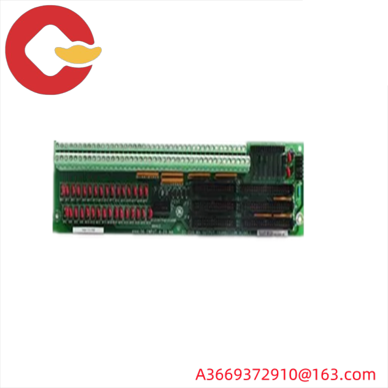
DS200CTBAG1ADD is a terminal board designed for use in GE Mark V Speedtronic systems. The Speedtronic family was created by General Electric to control large and small gas and steam turbine systems. MKV can be designed as a Simplex or TMR/triple modular redundant architecture to meet the needs of interconnected turbine systems. These boards are no longer manufactured and distributed by GE, but can be purchased as fully tested and refurbished models through AX Control. The Mark V turbine control system family to which this DS200CTBAG1ADD printed circuit board belongs is considered a legacy product family, as it was discontinued many years after its initial release. This DS200CTBAG1ADD printed circuit board, or PCB for short, is not an original product of the intended functionality of its particular Mark V series; This will be the DS200CTBAG1 Analog Termination Module missing all three significant product versions of the DS200CTBAG1ADD device.

Hardware tips and specifications

The DS200CTBAG1ADD is a long, narrow circuit board with only a few types of components. It drilled holes in each corner and long side to allow for the installation of hardware and other connections. Two of the holes are surrounded by conductive material. The voltage regulation in the assembly of this DS200CTBAG1ADD printed circuit board product is mainly handled by its standardized Mark V series voltage limiting hardware components; This DS200CTBAG1ADD PCB’s regular Mark V series assembly is clearly specialized with several red coated diodes. The board is marked with an identification number, including the board ID number and the company logo. DS200CTBAG1ADD is an analog terminal module. It is usually located within the <R5> kernel. The board has multiple connectors, including two COREBUS connectors (JAI and JAJ). The DS200CTBAG1ADD has two double stack terminal strips located on a long board edge with multiple connectors on each terminal board. There are 5 vertical pin cable connectors, 2 vertical pin connector connectors, and a 9-pin male serial connector. Fortunately, for this DS200CTBAG1ADD personalized product page, the various connectors for this DS200CTBAG1ADD PCB are described in detail in the manual materials available for this DS200CTBAG1ADD device. Each of these connectors comes with its own factory-printed naming label. Some of the connectors for DS200CTBAG1ADD PCB include:

8PL STCA board IONET connector
JAA TCCA board 4-20 mA output signal connector
JAI COREBUS connectors
JAJ COREBUS connector
JBB TCCA board 4-20 mA input and shaft voltage/current signal connectors
JEE STCA board COREBUS signal connector
JPC TCPD Board 24 V DC power signal connector
JX TCDA board IONET signal connector
6PL connector
All connectors listed above in this DS200CTBAG1ADD terminal module assembly have been named by their individual factory-printed naming labels, specific Mark V Series compatible products and interface opportunities, and a combination of specific Mark V turbine control system family applications and functions. The 6PL connector in this DS200CTBAG1ADD PCB assembly has not yet been named because it exists as a vesitigial structure that is normally not used during the normal function of the DS200CTBAG1ADD device. Other components on the DS200CTBAG1ADD include a resistor network array, relays, transistors, more than 20 metal oxide varistors (MOV), a dozen jumper switches, and many capacitors and resistors.

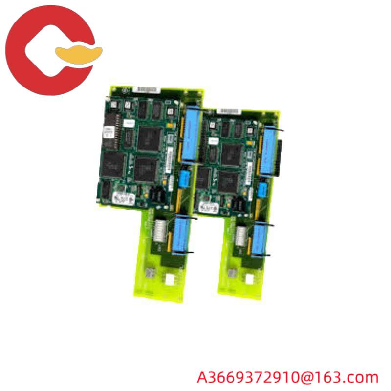
General Electric DS200CPCAG1ABB Contactor Pilot Card

DS200CPCAG1ABB|The contactor guide plate is manufactured by General Electric

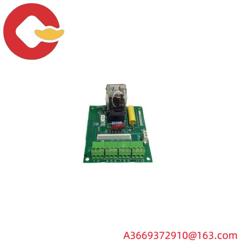
As mentioned earlier, this DS200CPCAG1ABB printed circuit board product was manufactured for GE’s now obsolete Mark V legacy family of turbine control systems. The Mark V series of this DS200CPCAG1ABB printed circuit board, or PCB for short, is considered a traditional product family because it had to be discontinued for many years after its first release. While the larger Mark V series of this DS200CPCAG1ABB PCB is a legacy series, it is also one of the final in GE’s Mark product line, leveraging its patented Speedtronic control system technology. The technology was first released in the late 1960s along with the concept of the Mark I series. The DS200CPCAG1ABB PCB is defined in the original printed Mark V Series instruction manual material as a contactor navigation board, although the product initially developed with a specific functional role will be the DS200CPCAG1 parent contactor navigation board. However, the triple revision history of this DS200CPCAG1ABB PCB is missing, consisting of two functional product revisions and a single artwork configuration revision.

Hardware tips and specifications

As with any Mark V Series product offered to us for both new and refurbished stock, the contactor navigation board functionality of this DS200CPCAG1ABB PCB was introduced by accepting various functional induction hardware components in its components. The GE contactor navigation pad DS200CPCAG1ABB has one 12-pin connector and two 2-pin connectors. It also has 4 terminals and can connect up to 12 signal wires. The GE contactor navigation board DS200CPCAG1ABB also has a 24VDC 15A socket power relay. According to the original operating instructions of this DS200CPCAG1ABB device, the various contactor elements of this DS200CPCAG1ABB PCB have a specific coil voltage of 115 V dc. Given this specific voltage, the DS200CPCAG1ABB contactor navigation board is capable of converting the input 115 V AC voltage to 105 V DC voltage, applying the full voltage to close its contactor assembly. The high voltage used in the DS200CPCAG1ABB product assembly means that its contactors remain closed after the initial closure. Voltage regulation in the components of the DS200CPCAG1ABB Mark V Turbine Control System family is handled by the various voltage limiting hardware components that their components possess, including various rectifiers, capacitors and diodes. The components of this DS200CPCAG1ABB PCB have a thick normal style PCB surface coating, which enhances the damage to everyday wear.
General Electric DS200CPCAG1ABB Contactor Pilot Card

There are moving parts inside the relay, so careful consideration is needed when installing the board in the driver. If the relay strikes the metal structure or other components in the drive cabinet, it is easily damaged. And the relay is tall, protruding from the surface of the plate and easy to hit. When sliding the board into the drive cabinet, ensure that you have a good view of the board and the interior of the cabinet. Slowly insert the board and align it with the screws on the rack. Insert the screw into the hole with one hand and turn the screwdriver with the other hand to secure the screw. However, do not damage the board by securing it so tightly that the screws will crack it. If the gasket is supplied or used on a defective circuit board, use a gasket. Then, unscrew the junction box and insert the wire into the corresponding terminal. Insert the wire into the terminal with one hand and tighten the terminal screw with the other hand. Hold the connector of the cable and plug it into the corresponding connector. Gently press them into the connector to ensure they are fully in place.

FAQ about DS200CPCAG1ABB
How to find capacitors on DS200CPCAG1ABB?
The capacitors of the DS200CPCAG1ABB are located in the center of the DS200CPCAG1ABB board. The capacitors on the DS200CPCAG1ABB are dark red.
How many amps does DS200CPCAG1ABB have?
The DS200CPCAG1ABB has 10 amps at 250 volts, and the DS200CPCAG1ABB has 10 amps at 30 volts.
What is the size of DS200CPCAG1ABB?
The DS200CPCAG1ABB measures 4 x 3.5 inches.

GE DS200ADPBG1ABB: Precision Engineered for Industrial Control Systems

DS200ADPBG1ABB|Genius adapter board

The DS200ADPBG1ABB Genius adapter board is a board supplied by General Electric, which is somewhat mysterious in addition to its description of its function as a Genius adapter board and its original belonging to GE’s Mark V Series turbine control system. While it can be loosely defined as a GE product, the Mark V series was most likely originally manufactured by a shell company of GE, such as GE Drive Systems or GE Industrial Control Systems. Before deciding to buy this DS200ADPBG1ABB Mark V Genius adapter board, consider the fact that this product takes full advantage of all three of its possible important product versions, which may significantly change its originally indicated performance specifications and dimensions.

Hardware tips and specifications

As with any Mark V Series product, this DS200ADPBG1ABB Genius adapter board uses a unique and enhanced family of hardware components and component specifications to achieve its intended function. First, the Genius I/O adapter board DS200ADPBG1ABB has an 8-switch block for configuring the board. The Genius I/O adapter board DS200ADPBG1ABB also comes with a 40-pin connector and a 26-pin connector. The third and final visually recognizable hardware element is crucial to this DS200ADPBG1ABB Genius adapter board, its family of manually removable hardware jumbos that have been included in its components for the highest customization purposes. The information stored on this personalized DS200ADPBG1ABB product page is about the range of information that can be retrieved from the inspection of available DS200ADPBG1ABB manual materials. Having said that, you can still get a lot of information from the DS200ADPBG1ABB product number itself (beginning with the DS200 series label). This series label has dual naming responsibility for this Mark V series product; Indicates that it is a domestically manufactured GE product with normal assembly type. Some additional information revealed in the DS200ADPBG1ABB Feature Product number for this DS200ADPBG1ABB Genius adapter board includes:

ADPB Functional acronym
A normal PCB coating style
Group A 1 Mark V Series Group
Level A and Level B functional revisions
Class B draft revision
GE DS200ADPBG1ABB: Precision Engineered for Industrial Control Systems
Before making any final purchase decision on the DS200ADPBG1ABB Mark V Series products, it is most important to be aware that the originally introduced specifications and dimensions stored on this DS200ADPBG1ABB feature product page may be subject to change due to their aforementioned feature and illustration configuration revisions. To help implement a convenient and safe DS200ADPBG1ABB board installation practice in its larger Mark V Series automatic driver assembly, the substrate of this DS200ADPBG1ABB PCB has been factory drilled in multiple locations, and each of these GE holes appears to be surrounded with insulation. Most likely to comply with potentially destructive DS200ADPBG1ABB plate surface voltages. Typically, the voltage protection and suppression strategy of this DS200ADPBG1ABB printed circuit board involves its normal Mark V series components accepting multiple standardised voltage limiting hardware components in series, including various capacitors, resistors, and integrated circuits.

FAQ about DS200ADPBG1ABB
What type of components does the DS200ADPBG1ABB Genius adapter board have?

This DS200ADPBG1ABB Genius adapter board has a normal assembly type, as evidenced by the DS200 label in its DS200ADPBG1ABB functional product number.
Is this a large model of a GE printed circuit board?

While this DS200ADPBG1ABB Genius adapter board isn’t the largest GE printed circuit board, it’s a pretty clunky model given its unique “L” shape.

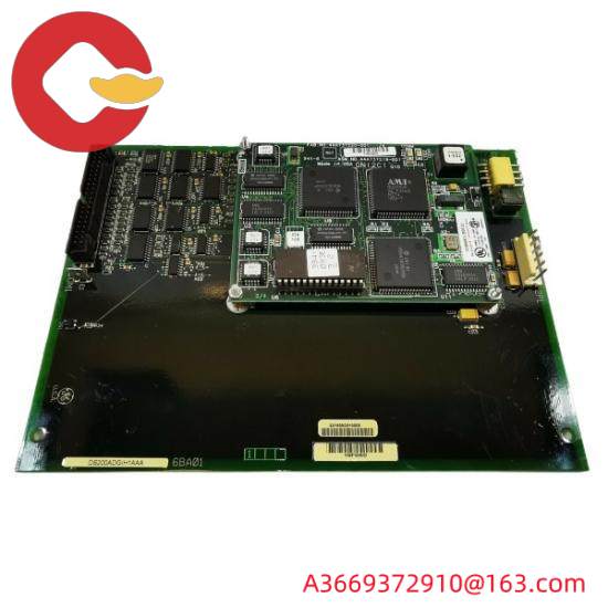
GE-FANUC DS200ADGIH1AAA Circuit Card: High-Performance Industrial Control Module

DS200ADGIH1AAA|The auxiliary interface board was manufactured by General Electric

General ELectric’s DS200ADGIH1AAA product is a printed circuit board originally manufactured for the Mark V family of turbine control systems, as described in the brief product description above. This DS200ADGIH1AAA printed circuit board, or PCB for short, the Mark V series, as you might have guessed from its full extended series name, has a range of specific applications in the management and control systems of GE compatible steam and gas turbine automation drive components. The Mark V series featuring this DS200ADGIH1AAA device, while related to newly developed turbine control applications, can still be considered obsolete overall, as it is GE’s legacy product line, discontinued in the years after its initial release due to obsolescent feature lines introduced by retailers. While generally obsolete, the Mark V was one of the last product families developed by GE, leveraging the patented Speedtronic control system technology that first appeared with the introduction of the previous Mark I series in the mid-to-late 1960s.

Hardware tips and specifications

As with any product offered in the Mark V family of turbine control systems, the intended functionality of this DS200ADGIH1AAA device is introduced by accepting a range of specialized hardware components and component specifications for its normal Mark V Series components. The GE auxiliary interface board DS200ADGIH1AAA has a 40-pin connector, 60 jumpers, and a 6-pin connector. The GE auxiliary interface board DS200ADGIH1AAA is also equipped with multiple test points. The board is 8 inches wide. The DS200ADGIH1AAA is 6 inches long and is designed to be installed in the driver’s board cabinet. It has four screws, which are aligned with the position of the board frame for installation with screws. As mentioned earlier, this DS200ADGIH1AAA product belongs to an older product family that is now obsolete. Because of this, it is not surrounded by any large amount of original printed online instruction manual material. In this case, the DS200ADGIH1AAA functional product number itself can be identified as a good primary source of hardware component and component specification information for the DS200ADGIH1AAA Board; Code specific details in a collection of functional named segments for the design. For example, the DS200ADGIH1AAA functional product number contains details about the normal Mark V series components of this PCB, its conformal coating style, and its three-fold product revision table, including three seemingly identical Class A product revisions.

The test point in the DS200ADGIH1AAA device assembly provides a method for testing the circuit on the board. However, only a qualified service provider can test the board. The vendor must have test equipment calibrated and designed for the task. The controls must be set up correctly, and the probe must be designed to work with the tester. Place the development board on a flat surface and place a protective bag under the development board. In addition, due to the risk of static electricity from DS200ADGIH1AAA Board service providers, a wristband must be worn at all times. When the wristband is properly installed, one end of the wristband is attached to your wrist and the other end is clipped to the metal leg of the workbench or table. It can also be attached to other metal structures. Static electricity is attracted to the metal ground and leaves the circuit board or your body. Another appropriate step to reduce static buildup is to avoid moving around while holding the board in your hand. The friction of walking causes static electricity to build up. This is especially true in cool, dry weather conditions. If you don’t have a wristband, you can also touch the static bag with the board onto a metal structure, such as a chair or metal table leg.

FAQ about DS200ADGIH1AAA
What is the size of DS200ADGIH1AAA?
The DS200ADGIH1AAA is 8 inches wide. The DS200ADGIH1AAA is 6 inches long.
How is the claw on DS200ADGIH1AAA marked?
The insert claw on DS200ADGIH1AAA is marked with EG1-EG4. On DS200ADGIH1AAA, they are located in a square format on DS200ADGIH1AAA.

GE FANUC DS200SDCCG1A - High-Performance Drive Control Module for Industrial Automation

DS200AAHAG2A|ARCNET HUB LAN driver board

The DS200AAHAG2A is a MARK V LM Speedtronic ARCNET HUB LAN driver board. The board was originally created by GE, but is now a traditional series module that no longer receives any support from GE. Nonetheless, AX Control does try to keep that board in stock when there is an available surplus in the market. Although a legacy series, the larger Mark V series of this DS200AAHAG2A PCB is also considered to be one of the last products in GE’s Mark product line, utilizing their Speedtronic control system technology, which first appeared in the launch of the Mark I series in the late 1960s. The DS200AAHAG2A ARCNET HUB LAN driver board was not originally developed, its function appeared in the Mark V series; It will be A DS200AAHAG2 parent ARCNET HUB LAN drive board that lacks this DS200AAHAG2A device standard Class A feature product revision.


Hardware tips and specifications


The DS200AAHAG2A is also known as the ARCNET Connector Board (AAHA). It is made as part of the control panel in the Mark V system. The AAHA board is able to connect external devices to the control engine, which is part of the <R> Core. It uses an ARCNET connection to do this. The <R> kernel actually uses two of these boards for slightly different purposes. An AAHA board is used to facilitate Stage Link between different operator interfaces and <R> kernels. Another AAHA board is used to grant <R> core communication to the COREBUS network. Establishing this connection facilitates communication between the control engine and the I/O kernel within the <R> kernel. The board is also connected to the PANA board using APL connectors. DS200AAHAG2A (AAHA) features the following:


Two connection ports.

The other two ports on the right, labeled P1 and P2, are ARCBNC-B and ARCBNC-A.

Below the P1 connector is a 2PL connection. The lower right corner of the board is an APL 10-pin connector that provides a communication link between the AAHA board and the board that contains the ARCNET driver in the <R> kernel.

As with any individual hardware component in this DS200AAHAG2A printed circuit board assembly, each of these connectors comes with its own factory-printed naming label for easy identification. Some of the connectors included in this DS200AAHAG2A device in addition to the APL connectors include 2PL TCPS board R-core connectors, ARCBNC A and ARCBNC C ARCNET BNC connectors, and EBNC and EPL connectors. Each of these connectors is named by combining their functionality in the Mark V Series automatic drive components, the aforementioned naming labels, and their interface potential with other PCBS. The EBNC and EPL connectors in this DS200AAHAG2A PCB assembly have not yet been named, as they are both residual structures designed not to be used during the normal function of the DS200AAHAG2A PCB and its larger automated drive assembly. The DS200AAHAG2A device, part of the Mark V family of turbine control systems, offers a number of hardware features for analyzing the embedded function segment of the DS200AAHAG2A function product number itself. For example, the DS200AAHAG2A functional product number begins with a dual-function DS200 series label, which is used to indirectly describe the normal Mark V Series assembly version of this DS200AAHAG2A device and its original GE manufacturing location. Through diligent analysis led by technicians, through careful analysis of this DS200AAHAG2A functional product number, some other relevant pieces of hardware information were revealed, This includes the AAHA functional product acronym for DS200AAHAG2A ARCNET connectors, normal PCB coating styles, A second set of Mark V Series product groupings, and finally a single Class A functional product revision.


FAQ about DS200AAHAG2A

Is the DS200AAHAG2A the only AAHA board used in the <R> kernel?


No, the < R > kernel uses two AAHA boards. The DS200AAHAG2A can be one of the AAHA boards used in the < R > kernel, but there must be another AAHA board.

Where can I see the DS200AAHAG2A chart?

You can find the DS200AAHAG2A drawing in Figure 6353 of the Mark LM Turbine Control Manual – Manual GEH-5.2. This DS200AAHAG2A diagram in the manual depicts the DS200AAHAG2A in a simple way and shows all the connections and functions of the DS200AAHAG2A.

What hardware does the DS200AAHAG2A use?

The DS200AAHAG2A requires no hardware or software configuration to install in the control system.

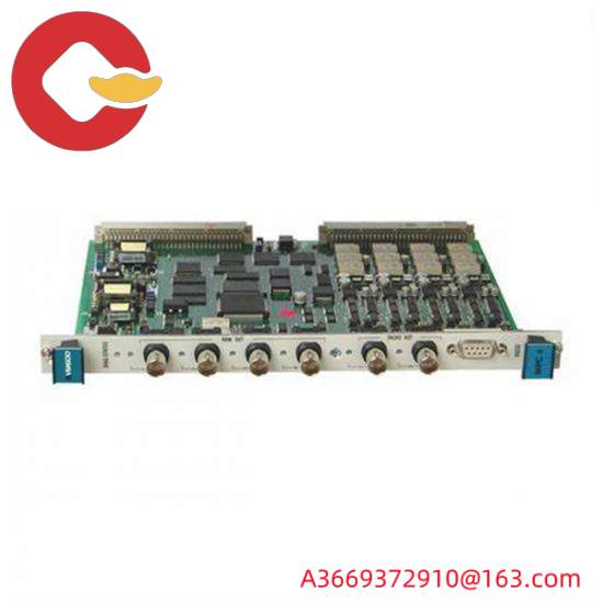
Vibro-meter VM600 CPU Module 200-595-031-111

VM600-CPUM|VM600 frame meter

The VM600Mk2 CPUMMk2 + 1OCNMk2 rackcontroller and communicafions interface moduleis designed for operation with the secondgeneration of VM600Mk2 rack-based machineryprotection system (MPS), from Meggitt’svibro-metere product line. TheCPUMMk2 + IOCNMk2 module consists of centralprocessing unit (CPU) and input/output(interface) modules that act as a systemcontroller and data communications gateway forVM600Mk2 systems.
VM600Mk2 rack-based monitoring systemsThe vibro-meter® VM600Mk2 rack-basedmonitoring system is the evolution of Meggitt’ssolution for the protection and monitoring ofrotating machinery used in the power generationand oil & gas industries.VM600Mk2 solutions arerecommended when a centralised monitoringsystem with a medium to large number ofmeasurement points(channels)is required.lt istypically used for the monitoring and/orprotection oflarger machinery such as gassteam and hydro turbines, and generators,smallermachines such as compressors, fansmotors,pumps and propellers, as well as balanceof-plant (BOP)equipment.
A VM600Mk2 system consists of a 19″ rack, a rackpower supply and one or more monitoringmodules.Optionally,relay modules and rackcontrollerand communications interfacemodules can also be included.
Two types of rack are available: a VM600Mk2system rack (ABE04x,6U) that can house up totwelve monitoring modules, and a VM600Mk2slimline rack(ABE056,1U) that can house onemonitoring module.The racks are typicallymounted in standard 19″rack cabinets orenclosures installedin an eauipment room,
Vibro-meter VM600 CPU Module 200-595-031-111
Different VM600Mk2 monitoring modules areavailable for machinery protection, conditionmonitoring and/or combustion monitoringapplications.For example.the
MPC4Mk2 + 10C4Mk2 module supports bothmachinery protection and condition monitoringthe XMV16+ Xl016T module supports extendedcondition monitoring for vibration and theXMC16+X1016T module supports extendedcondition monitoring for combustion.
Note: For the MPC4Mk2 + 10C4Mk2 machineryprotection and condition monitoring module. themachinery protection functionality is available bydefault, while the condition monitoringfunctionality is optional and depends on thepurchased VibroSights software license.
The RLC16Mk2 relay module is an optional moduleused to provide addifional relays when the fouruser-configurable relays per MPC4Mk2 + 10C4Mk2module are not sufficient for an application.
The CPUMMk2 + lCNMk2 rack controller andcommunications interface module is an optionalmodule used to provide additional yM600Mk2system functionality such as fieldbus
communications(ModbusTCP and/orPROFBUS DP); module data aggregation,processing and sharing:rack and/or fieldbuscommunicationsredundancy:front-panel alarmreset (AR); MPS rack (CPUx) security: system eventand measurement event logging.
VM600Mk2 rack-based monitoring systemscomplement the vibroSmart distributedmonitoring systems that are also available fromMeggitt’s vibro-metere product line, and arecompatible with the same VibroSight” machinerymoniforing software suite.

VM600 IOC4T
VM600 RPS6U
VM600-204-040-100-012
VM600-ABE040
VM600-ABE042
VM600-AMC8
VM600-ASPS
VM600-CMC16
VM600-CPUM

Search for products

Back to Top
Product has been added to your cart