

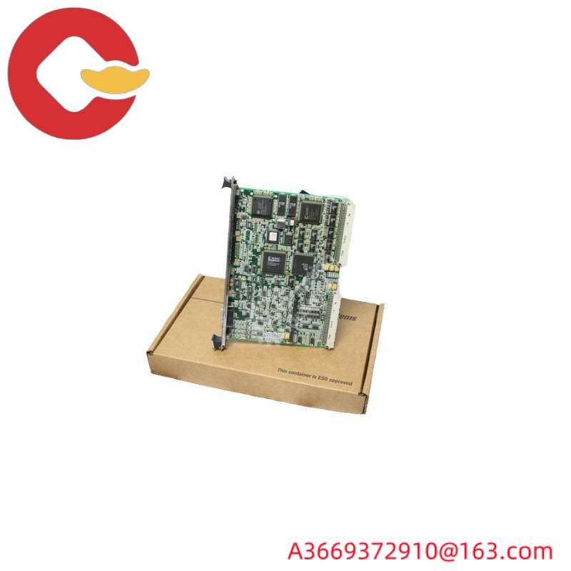
DS200TCRAG1ACC|The relay output board is designed for use in Mark V Series turbine control systems
The DS200TCRAG1ACC printed circuit board from General Electric was originally developed as a member of its Mark V family of turbine control systems. As its full extended series name attests, the Mark V series to which this DS200TCRAG1ACC product belongs has specific applications in the management and control systems of compatible steam, wind and gas turbine automation drive components, and as it was eventually discontinued within a few years of its initial release, Therefore, it is considered to be a legacy series of GE. The DS200TCRAG1ACC printed circuit board, or PCB for short, the Mark V series, while a legacy family of GE, is also considered one of the last GE Mark product lines, leveraging the brand’s patented Speedtronic control system technology. The technology was first introduced in the late 1960s with the introduction of the Mark I. This DS200TCRAG1ACC PCB is more suitable to be defined as a relay output board; The original functional product description is the same as the original product description. Mark V Series teaching manual materials. While this DS200TCRAG1ACC PCB can be defined as a relay output board, the first product developed with this feature in the Mark V will be a DS200TCRAG1 relay output board that lacks three significant revisions of the DS200TCRAG1ACC product.
Hardware tips and specifications
Like anything offered by GE’s Mark V family of turbine control systems, the DS200TCRAG1ACC PCB leverages its own specific feature set – introducing hardware components and component specifications. The GE relay output board DS200TCRAG1ACC contains 30 plug-in relays. It also features four 34-pin connectors and four 12-pin connectors. The ids assigned to the 34-pin connector are JOR, JOS, JOT, and JO. The ids assigned to 12-pin connectors are JS3, JS4, JS5, and JS6. For convenience, the DS200TCRAG1ACC instruction manual available in the manual TAB above describes in detail the purpose of each connector listed here. Although this DS200TCRAG1ACC product cannot be configured with software, hardware configuration and customization for this DS200TCRAG1ACC PCB can be made using the DTBC and DTBD optional printed circuit boards from the Mark V Turbine Control System family. The DTBC and DTBD boards, which are important to the customisation of this DS200TCRAG1ACC product, are also considered members of the GE Mark V turbine Control system family and can be repaired or replaced at AX Control. Any relay that can be used for this DS200TCRAG1ACC printed circuit board assembly is made from signals received from the CSP of the larger Mark V series automatic drive assembly and then operated through a range of applications of the related circuit board, including DTBC, DTBD, TCRA and TCDA printed circuit boards; All of these are available through our website.
Because there are multiple connectors on the GE relay output board DS200TCRAG1ACC, guidelines must be followed to ensure that you can quickly connect the cable to the correct connector on the replacement board. Before starting the replacement, make sure you know the location of the emergency shut-off device for the current supplied to the drive. Moreover, you must know how to make the shutdown device and verify that it is in good working order. Those who are familiar with driver installation will know the details about power supply and emergency cutoff. The next step is to verify that the floor in the area around the drive is clean and free of moisture or standing water. Use a cleaner to clean oil or grease from the floor. You should also remove all ungrounded two-core power cords because of the risk of electric shock. It is best practice to inform workers and managers of other equipment in the work area of scheduled work so that they can plan for work disruptions and plan for them. Choose a clear, flat, and sturdy workspace near the drive, then place the frame containing the circuit board on it. Before making any final purchase decision on this DS200TCRAG1ACC product, you must be aware that its originally interpreted performance specifications and dimensions will almost certainly be affected by its full triple revision history of adoption.
FAQ about DS200TCRAG1ACC
What does DS200TCRAG1ACC use?
The DS200TCRAG1ACC is used with a digital I/O core of three gas turbine control processors, or the DS200TCRAG1ACC is used with a general-purpose data processor. These kernels used by DS200TCRAG1ACC are < QD > or < CD >.
How many relays are there on DS200TCRAG1ACC?
There are 30 plug-in relays on DS200TCRAG1ACC.
What is the contact rating of the relay on DS200TCRAG1ACC?
Each relay on the DS200TCRAG1ACC has a 0.5 amp contact rating.